Programming, Software

Bit Depth Problems with RMagick / ImageMagick

I just spent the entire afternoon debugging a problem I couldn’t find elsewhere, so I’m documenting it in the off chance someone else runs into the evil thing.

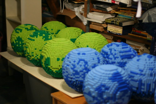
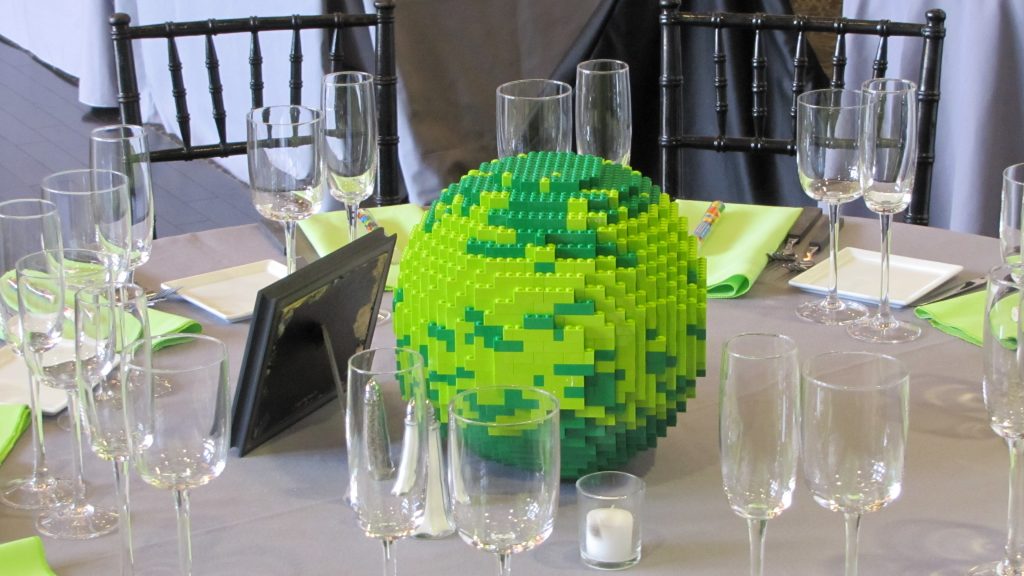
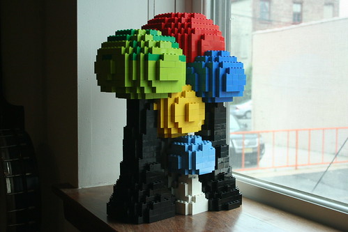
I’m composing some images on the fly using ImageMagick via RMagic. It grabs one file, floods the image with a given color, and layers another on top of it. Locally, it works great, and gives me “body parts” like this one:

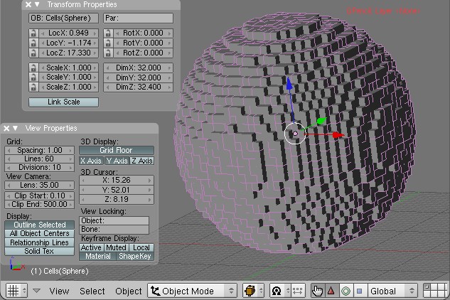
Unfortunately, when I push the code to Heroku, it starts going through a goth phase and filling everything in with BLACK LIKE SOUL:
I spent a very, very long time trying to suss this one out, checking out everything from opacity to gem versions. Finally, I checked the ImageMagick version (Magick::Magick_version).
Local: “ImageMagick 6.6.7-1 2011-02-08 Q8 http://www.imagemagick.org”
Heroku: “ImageMagick 6.6.0-4 2010-06-01 Q16 http://www.imagemagick.org”

Ok, so Heroku’s is a bit older. But that’s not the critical issue. The bigger problem is the Q16, which is reporting the quantum depth. I don’t understand nearly enough about image processing to talk about what that really means. But long story short, it means my images had different default bit depths and it was causing everything to blow up. Or something.

I was able to fix it by changing how I instantiated the Pixel for the fill. Before, I was using

fill_image.colorize(1,1,1,Magick::Pixel.new(r,g,b))

where r, g, and b are integers between 0 and 255.

Conveniently, RMagick has added a from_color method to Pixel, which lets you define a pixel based on a color name. I passed in a hex value, and everything magic(k)ally works normally again:

color = '#ababab'
fill_color = Magick::Pixel.from_color(color.upcase)
fill_image = fill_image.colorize(1,1,1,fill_color)

I wish I understood a few more of the particulars about what is really going on here. But for the time being I need to move on to finishing this up. Any insight is welcome in the comments.

DIY Lego Wedding Centerpieces
LEGO

Lego Sphere Factory

This weekend was spent at RevolvingDork’s parents’ house, which they kindly let us turn into a Lego sculpture factory.

Basement Spheres

We had a total of 12 people over on Saturday attempting to make 15 Lego spheres. Each sphere is about 25cm (10ish inches) in diameter. They follow a pattern I created using Blender and the techniques/scripts described here and here.

We used a lot of Legos. Approximately 22,000. Most of them were sourced from BrickLink, though we did buy a few sets new from Toys R Us. When build day came we realized we didn’t have enough, so RD made a last-minute trip to the Lego store. He was able to talk the staff into letting him buy a few boxes in bulk.

Legos

In order to make the build process easier, we laser-cut jigs out of foam core for each of the 27 layers. The jigs served as templates for each layer, avoiding the frustrating and time consuming counting I had been doing when building them earlier. We didn’t use a script to output the vector cut paths, RD just traced them by hand in Illustrator.

Building with a jig

To put it plainly: assembling these is hard. There are lots of overhangs and ragged edges where you really need a 1×1, but of course those aren’t very structurally stable. The first few layers are definitely the hardest, and there are a number of tips and tricks we figured out along the way to make things easier. And by easier I mean possible.

The spheres were built mostly hollow, though thicker at the top and bottom for structural support. A few folks incorporated a center column to make placing the top easier. Personally I found it easier to start thickening the walls around the top 1/3rd and using long 2×8 pieces to mesh in the top.

John decided to get fancy with his; rather than a simple mottled pattern he made an artistic swirl.

John and Sphere;

After 12 hours of work on Saturday we had 6 complete spheres and a number of half-finished ones. On Sunday RD, myself, and my soon-to-be mother-in-law finished up the leftovers, for a total of 13 spheres completed this weekend. I’m pretty impressed, and honored to have the sort of friends who would give up their Saturday to assemble these ridiculous sculptures.

These were used as the centerpieces in our wedding, and the ones that survived the evening intact were given to family and friends (with first dibs going to those who made them).

DIY Lego Wedding Centerpieces

Programming, Software

LEGO plans, now with better rendering

You may remember the “Legoizer” script I’ve been working on for Blender. It uses an existing script and one I’ve created to generate “layers” of LEGO patterns for building.

I got a lot of great suggestions on my last entry for how to automate the process of taking a screenshot, but sadly when it came down to implementing them things didn’t go so well. Luckily Angelo from Abandon Hope Games was kind enough to take the time to help me get the environmentals in Blender set up just right for rendering a “pattern slice.”

Step 0: Start with an object made of objects
The AddCells script uses DupliVerts to create an object made of references to another object. We’ll get to that in a minute, but first, let’s assume you have an object:

Step 1: Set up the camera
We want the camera to be facing down and rendering orthographic(all lines parallel) rather than perspective.

Make sure you’re in Object Mode and select the camera.
Press Alt+G and then Alt+R (confirming the dialogs) to return it to the origin.
Hit F9 to get into the Editing panel
Click the button labeled Orthographic in the Camera tab

Press 1 on your number pad to get a side view of the scene. Click the blue transform handle of your camera and move it up along the Z axis so it is well above your object.
Press 0 on your number pad and you should see a rectangular bounding box around your object (or perhaps around nothing) which represents the are which the camera sees.
Scroll the “lens” option right above the Orthographic button to zoom in/out so your

If you do a test render now with F12, you’ll probably see a badly lit (perhaps almost all black) render of your object from the top down.

Step 2: Set up the lighting

Select the existing light in your scene and press x on your keyboard to delete it.
Press space bar to bring up a dialog, and go to Add > Lamp > Sun
It doesn’t matter where the lamp is, as long as it’s facing down (which it is by default).

Step 3: Configure your materials

I mentioned earlier that our object was made up of DupliVerts.
These aren’t “real” objects, which is why I had such trouble applying materials to them. You need to apply the material to the reference object, which is generally somewhere in the middle of it. I usually do this by switching to the Outliner menu and finding the source cube manually.

Once we have our source object selected, hit F5 to bring up the Shading panel and click Add New under Links and Pipeline.
Pick a new color for your object. This will be the color of the lines in your final rendered image, so pick something that contrasts with your background color (which defaults to blue).
Click the Wire button under Links and Pipeline

Your object in the viewport should take on the color you’ve selected. If if doesn’t, you probably didn’t select the correct source object.

Hit F12 to render. Viola!

Now that we have our environment set up the way we want, rendering via script is easy. I’ve updated the script source (now on gist) to call Render when it’s done slicing and save the file to my hard drive.

This all works great, but of course there’s a new problem. Since we want to iterate over the entire object, I need to “reset” it back to being whole again. While I’ve saved an undo point I don’t think you can call that point via the API. In the current iteration of the script I save the vectors of each vertex before deleting it and then call verts.extend to add them back. This works great except…

The vectors for the verticies are transformed to be in the selected object’s local space, which is necessary for “layer 1” to be the first layer of the object and so forth. Unfortunately I haven’t yet figured out how to transform those verticies back. So when I run the script it dutifully reassembles my sphere originating from the center of the object. So there’s still some work to be done there.

Yaaaay... oh.

Programming, Software

Faking Blog Integration With XMLRPC and Ruby

I’m rebuilding indiecraftshows.com in RoR, but the blog will stay on WordPress. The rails app will be hosted on Heroku, and the blog will stay where it is at NearlyFreeSpeech.net. There’s one catch: I want the latest blog post to appear on the home page, which is part of the rails app.

To do this I’m using ruby’s included XMLRPC library to grab the latest post from WordPress and shove it into a YAML file named with the date and post ID. This happens in a cron job run daily. Since I only care about showing the most recent post, I don’t bother to check to see if there are other posts I don’t have.

I created a really simple object called (creatively) BlogPost, and chucked it in with the rest of my models in app/models. Note that BlogPost doesn’t inherit from ActiveRecord.

require 'xmlrpc/client'

class BlogPost
  def self.latest
    Dir.chdir(Rails.root.join('blog'))
    post_files = Dir["*.yaml"]
    most_recent_file = post_files.sort.last
    YAML::load(File.open(most_recent_file))
  end

  def self.fetch
    server = XMLRPC::Client.new2('http://www.kellbot.com/xmlrpc.php')

    blog_post = result = server.call("metaWeblog.getRecentPosts",1,YOUR USERNAME HERE,YOUR PASSWORD HERE,1)
    File.open(Rails.root.join('blog',"#{blog_post[0]["dateCreated"].to_time.to_i}-#{blog_post[0]["postid"]}.yaml"),'w') do |io|
      #we only want the published ones
      YAML.dump(blog_post[0], io) if blog_post[0]["post_status"] == "publish"
    end
  end
end

When the home page is called, the controller grabs the most recent yaml file (by name, not by time of creation, since WordPress allows you to lie about time). I just use the XMLRPC object as-is, but if I wanted to I could get fancy and do some post-processing to make it a little more friendly.

Gaming, Software

DSx86

Every now and then I come across something that I can’t believe someone has taken the time to write.

In this case, it’s a DOS emulator for the Nintendo DS, the DSx86.

As if there weren’t enough options for extending the DS (homebrew, NES emulation), one man has taken it upon himself to write a DOS emulator for the DS. It will run most games that run on a 286/386, with some caveats. Not all the opcodes have been written in yet, and sound blaster support requires a little bit of finesse. But it’s under active development, which is exciting.

You load a game the same way you did back in the day… from the command line. Since the DS doesn’t have a keyboard, DSx86 includes one for you on the touch screen. It’s hilariously adorable.

Once the game is loaded you can either continue to use the “keyboard” or swap screens so that your game is shown in the touchscreen and you can use the stylus as a mouse. Holding down left/right on the d-pad to click took a bit of getting used to. There’s also a tap-to-click mode, but I found it difficult to use for gaming. It was a good illustration of how programs not designed for a touchscreen can be infuriating to use on one. Because most DOS games run at a slightly larger resolution than the DS, you have the option of either panning or resizing the screen. I found panning to be the most useful, and all it really cut off was the title/menu bar at the top.

Seeing the old Sierra logo along with the MIDI-tastic intro music on the DS was ridiculous and awesome. I’m just about finished my 20th or so lifetime play through of The Island of Dr. Brain. If you’re dying to take some of your old DOS games with you (you did save them all, right?) , check the compatibility list and give DSx86 a try.

Crafting, lased, LEGO

Meta Lego Storage

In need of a way to organize and store my Lego obsession, I made a bunch of acrylic boxes which not only hold Legos, but also stack and interlock similarly:

Each brick box holds 64+ of the same-shape piece. So the 1×1 box will hold 64 1×1 bricks, and the 2×2 holds 64 2×2 bricks. The larger ones hold a few more due to how the sizing works out. The 1×1 box is 40mm per side (external dimensions).

I posted the patterns on Thingiverse should anyone wish to make their own. No,  I’m not going to make and sell them. They’re time consuming to make, and plus I’m pretty sure Lego would sue me. If you don’t have access to a laser cutter, I’d suggest using a service like Ponoko.

The patterns were generated in OpenSCAD using the following code. Change “rows” and “cols” to get the lego size you desire. By the way, I’m teaching a class on OpenSCAD in Brooklyn next weekend!

fundamental_unit = 0.8;
thickness =3;
h_pitch = 10;
v_pitch = 12;
tform = 5;
knob = fundamental_unit*h_pitch*tform;
module side(rows){
	lwidth = rows*fundamental_unit*h_pitch*tform;
	lheight = v_pitch*fundamental_unit*tform;
	difference() {

		square(size=[lwidth, lheight]);
		translate(v=[10,0,0]) square(size=[lwidth-20,thickness]);
		translate(v=[10,lheight-thickness,0]) square(size=[lwidth-20,thickness]);
		square(size=[thickness, 10]);
		translate(v=[0,lheight-10]) square(size=[thickness, 10]);
	translate(v=[lwidth-thickness,10]) square(size=[thickness, lheight-20]);
	}
}
module top(rows,cols,holes){
	lwidth = rows*fundamental_unit*h_pitch*tform;
	llength = cols*fundamental_unit*h_pitch*tform;
	difference(){
		square(size=[lwidth,llength]);
		square(size=[thickness,10]);
		square(size=[10,thickness]);
		translate(v=[lwidth,0,0]) square(size=[-thickness,10]);
		translate(v=[lwidth,0,0]) square(size=[-10,thickness]);
		translate(v=[lwidth,llength]) square(size=[-10,-thickness]);
		translate(v=[lwidth,llength]) square(size=[-thickness,-10]);
		translate(v=[0,llength]) square(size=[10,-thickness]);
		translate(v=[0,llength]) square(size=[thickness,-10]);
		if(holes==true){
			for (i = [1:cols]){
				for (j=[1:rows]){
				translate(v=[j*knob-knob/2,i*knob-(fundamental_unit*h_pitch*tform)/2,0]) circle(r=fundamental_unit*6*tform/2);
				}
			}
		}
	}
}

rows = 2;
cols = 4;

h_spacing =  rows*fundamental_unit*h_pitch*tform+10;
l_spacing =  cols*fundamental_unit*h_pitch*tform+10;
v_spacing = fundamental_unit*v_pitch*tform+10;

side(rows);
translate(v=[ rows*fundamental_unit*h_pitch*tform+10,0,0]) side(rows);
translate(v=[0,v_spacing]) side(cols);
translate(v=[ cols*fundamental_unit*h_pitch*tform+10,v_spacing]) side(cols);
translate(v=[0,2*v_spacing]) top(rows,cols,true);
translate(v=[ rows*fundamental_unit*h_pitch*tform+10,2*v_spacing]) top(rows,cols,false);

In the next batch I’m going to make the nubs a little smaller than the holes. They work now, but it’s a bit fiddly getting everything to line up just so. A little more forgiveness would be nice. Also, OpenSCAD does strange things with circles. Rather than simply write a circle in the DXF, it represents it as a bunch of line segments. I’m not sure if there’s a way around this, but it’s marginally irritating.

You can download a .dxf for a few different box sizes on Thingiverse.
I’ve also created a Flickr Collection for my various Lego stuff.

Meta Lego

Software

3D Modeling by Numbers: Learn to use OpenSCAD

Want to learn to create 3D models, but find the user interface for most 3D modeling programs too infuriating? OpenSCAD may be for you! And we’re  teaching a class on how to use it on Sunday, June 27!

OpenSCAD is “The Programmers Solid 3D CAD Modeler.” Rather than learn tricky user interfaces and navigate seemingly endless obscure menus, OpenSCAD uses a simple scripting language to generate 3D models from either existing or new 2D drawings. We’ll start in 2D (great for creating designs for the laser cutter) and move into 3D modeling (perfect for MakerBot!).

A basic understanding of computer programming is helpful but not required. Sign up at EventBrite today!

LEGO

More Legos From 3D Meshes

Mushroom Thingy

I’ve been doing more Lego building from models. This time I made sort of an abstract mushroom tree forest thing. More photos are available on Flickr.

Here’s the original model (left) and the resulting cubeified model after running it through AddCells (right):

I realized of course that with everything grey, it was very difficult to determine which bricks of which color were needed where. So I un-joined the primitives in the original model and ran AddCells on each one individually. I used different colored “cell” blocks for each one, and the resulting models kept the color:

Each peice needed to be moved a little bit so that all the blocks lined up, but other than that it worked pretty well.

Because each piece is separate, I couldn’t use the hide tool to “slice” each layer. But I did find out something interesting: each “cube” in the new models is actually a vertex. I honestly don’t understand a ton about how that’s pulled off, but basically instead of being a point on a line, each vertex represents another object, the source cube.

In order to slice up the model, I wrote a script to delete all but a given layer, with layer 1 being the bottom layer, up to however many layers of cubes are in the model.


import Blender, BPyMessages, BPyMesh
from Blender import Scene, Mesh, NMesh, Window, sys, Group, Object, Draw
from Blender.Mathutils import \
	Matrix, Vector, ProjectVecs, AngleBetweenVecs, TranslationMatrix

def trimToLayer(selected,layerNumber, blockHeight,offset):
        toDelete= []

        mesh = selected.getData(mesh=1)
        tmesh = NMesh.GetRawFromObject(selected.name)
        tmesh.transform(selected.matrix)
        #Delete verticies above the current layer
        for v in tmesh.verts:
            if v.co[2] > blockHeight*layer:
                toDelete.append(v.index)
        if layerNumber > 1:
                #Delete verticies below the current layer
                for v in tmesh.verts:
                    if v.co[2] < blockHeight*layer-1:
                        toDelete.append(v.index)        
        toDelete = list(set(toDelete))

        mesh.verts.delete(toDelete)
        Window.Redraw()

##################3
if __name__ == "__main__":
    selection = Object.GetSelected();

    layer = Draw.PupIntInput("Layer",1,0,100)
    Blender.SaveUndoState('Kill Everything')  
    print "\nTrimming First Layer"
    for s in selection:
	bbox = s.getBoundBox(1)
	print bbox[0][2]
	trimToLayer(s,layer,1.2,bbox[0][2])


There are a couple problems with the script: primarily, I couldn’t find a way to get the software to save a screenshot (ctrl+F3 normally). Because of this, I couldn’t loop through the whole thing at once, I had to go through one layer at a time, running the script, hitting ctrl+f3, saving the image, lather rinse repeat. It was tedious, though not as tedious as manually cutting up each layer. But almost.

The resulting MRI-like were used to build the model. The exact placement of which bricks and where is left as an excercise to the reader. A few layers (from the bottom, middle, and towards the top) are shown below.

This is my first attempt at a Blender script, and admittedly one of my first times using blender, so any feedback on how to streamline this process would be appreciated.

Programming, Software

Fixed: WordPress MU Uploaded Image Display Issues

Just a quick fix for something I couldn’t discount cialis without prescription find earlier:

If you’re on shared hosting which has PHP’s safe_mode enabled, you may run into problems with uploading images. Specifically, you can upload images just fine (assuming you’ve configured uploads correctly) but can’t see uploaded files. This is the case on NearlyFreeSpeech.Net (where my sites are hosted), and probably a few other hosts as well.

WordPress MU uses some .htaccess & PHP tomfoolery to obfuscate the real file path (among other things). Because safe_mode checks to see if the UID/GUIDs match on file_exists(), the script that fetches the images will fail and return a 404. Which is to say, the owner/group of the uploaded file is web/web (or whatever your server’s web user is), but since I manually uploaded the WPMU files originally, those are me/me. Since me != web, it failed. WordPress took this to mean the file was absent and returned 404.

On NearlyFreeSpeech, adding wp-content/blogs.php to the ‘web’ group was all it needed.