I don’t have a knitting machine problem, I could quit right now, I swear.
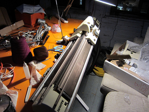
While working with my Toyota 747 I decided to try and find a ribber for it, which led me to the Ravelry Knitting Machine Sales group. I did not find a Toyota ribber, but I did find someone in Brooklyn who was selling a White/Superba 1602. He was selling it at a reduced price because the electronic selector box was not functioning.

The Superba knitting machines, which were also sold under the brand names White, Singer, and Phildar, are really interesting machines. Instead of a main bed and an optional removable ribbing bed like most Japanese machines, the Superbas have two permanently fixed identical beds. This makes it much easier to get consistent, even ribbing.
Mechanically, the machine is in good shape. Stockinette stitch, ribbing, and jacquard patterning (done by manually moving the needles into place) all work well.
The selector box, which can be seen in Patrick’s photo stream, works by reading stitch patterns off mylar sheets. A photoresistor detects either a light or dark square and sends a signal to the machine which moves the needles accordingly.
In addition to maintaining a comprehensive site on Superba machines, Patrick also was kind enough to supply me with the users manual, service manual, exploded part diagrams, and logic flow charts for the electronics.
As soon as I opened up the machine and took out the circuit boards, it was clear things weren’t working properly:

I superglued the board itself back together, and then used lumps of solder to repair the broken traces. Jumper wires would have been better, but admittedly I was too lazy to get up and find a spool of wire.
Once the traces were repaired, Phooky helped me test the output voltages. Since it takes in 110V mains power, I was nervous to start poking at it by myself. But we only made the electricity arc between the multimeter probes once. Have I mentioned that mains power is kind of terrifying?
Anyway, of the four pins that connect to the card edge, two are tied together to ground, and the other two provide 24v for the motor drive (which feeds the mylar sheets) as 12v for the COP420 microchip.
Speaking of the COP420, my first instinct was to try to get a firmware dump off the chip and try to reverse engineer the firmware. Not that I have any experience doing that, but luckily Trammell does. Unfortunately, he found out that the COP420 is a mask-programmed device, meaning that the program is put into ROM when the chip is created, in contrast to something like the Atmega chips used in Arduinos. If you’re lucky, the “test mode” on the chip was initially enabled, making it possible (if somewhat of a pain) to read out the firmware.
The more I think about it, the more it makes sense just to redesign the selector box from the ground up. Most of the bulk and power of the box is related to the scanning and advancing of the mylar cards, which are adorably archaic but not exactly convenient. A USB interface would be vastly preferable, and would cut down on about 2/3 of the circuit. I need to do some investigating to see if the whole thing could be USB powered, eliminating the need for a separate power cord and bulky transformer.
Yeah, ok, I have a knitting machine problem.