The biggest part of setting up our home network was wiring the house for ethernet. There were two basic phases: running the wire through the walls, and then terminating/testing each wire to make sure it was set up correctly. We hired a family friend who is an electrician to run the wires, and then terminated/tested them ourselves. We installed a total of 34 lines across 4 different floors, all coming into the closet under the staircase.

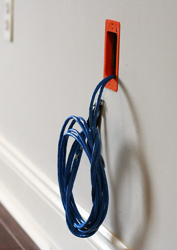
Running the wires proved to be a bigger challenge than expected due to the fact that all of our walls were filled with insulation. A number of access holes had to be cut in the drywall in order to access everything. Four separate boxes of Cat 6 ethernet cable were used, so that multiple lines could be run to the same location at once. The free end from each spool was taped into a small bundle and a long metal wire with a hook was run from the target location (say, the bedroom), through the walls, and into the basement where it was attached to the end of the cat 6 bundle. Then the wire was pulled back up through the walls, bringing the cat 6 cable along with it.
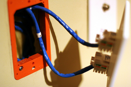
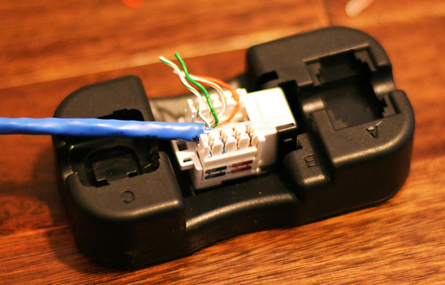
Each location in our house got either 2 or 4 wires, depending on how many devices we planned to put in that area. For every location in the house we needed either two or four RJ45 keystone jacks (one for each wire) and a faceplate with an appropriate number of holes. Keystone jacks are available in two basic formats: the standard kind which require a punch-down tool to terminate the wires and a “tool free” type which includes little caps which punch the wires down automatically. I personally prefer the standard jacks.

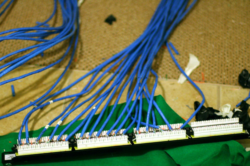
The opposite ends of the cables, which are bundled in the basement closet, get a slightly different treatment. Instead of going into individual jacks, they’re terminated in a patch panel. We used two 24 port patch panels, placing 16 connections on one and 18 on the other. We’ll be mounting these in our server rack, but if you’re going for a minimalist build there are inexpensive wall-mount brackets.
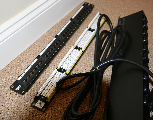
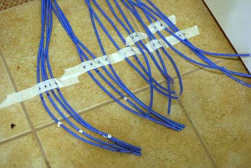
Each wire was marked with a small letter or number at both ends. To keep everything in order and save my sanity, I used masking tape to temporarily keep the wires in alphabetical/numerical order.
Each jack in the patch panel is then patched into one of our network switches (which are each in turn plugged into the router) with a 6″ cable. Why not just go directly from the wall to the network switch? The patch panel gives you flexibility to change the network around later by moving the 6″ patch cables rather than tangling up the spaghetti coming out of the walls. Additionally, punching the wires down into the back of the patch panel is considerably faster than crimping a male RJ-45 connector onto the end of each drop.
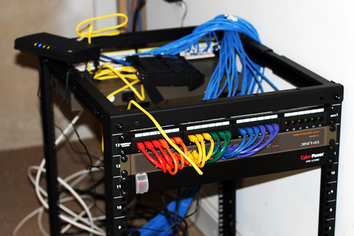
I briefly considered crimping my own patch cables from the leftover cat 6 cable, but then I remembered that crimping cable ends sucks and a 6″ patch cable costs all of $0.55. The photo above shows half our network cables, the other half are mounted on the back of the rack. I still need to install stress relief for the blue the cables and mount the router + modem nicely somewhere.
The server and switches are all connected to the LAN ports on the router. Our cable modem connection goes into the WAN port. Now the server and anything else on the LAN can see the outside world.
Overall it was a pretty massive project: it took three people a week to get all the wires in place and then another day and a half for my dad and I to button it all up. The next step is to configure the router for the advanced management options we want, as well as configure the wireless access points to provide “seamless” coverage throughout the house. The media server also needs considerable set up, right now it’s just a fresh Linux box with a giant hard drive. I’ll cover the software side of things in part 3 of Our Over-engineered Home Network.
This is part 2 of 3 posts about our home network.
Part 1: Our Overkill Home Network
Part 3: Coming soon
Comments are closed.